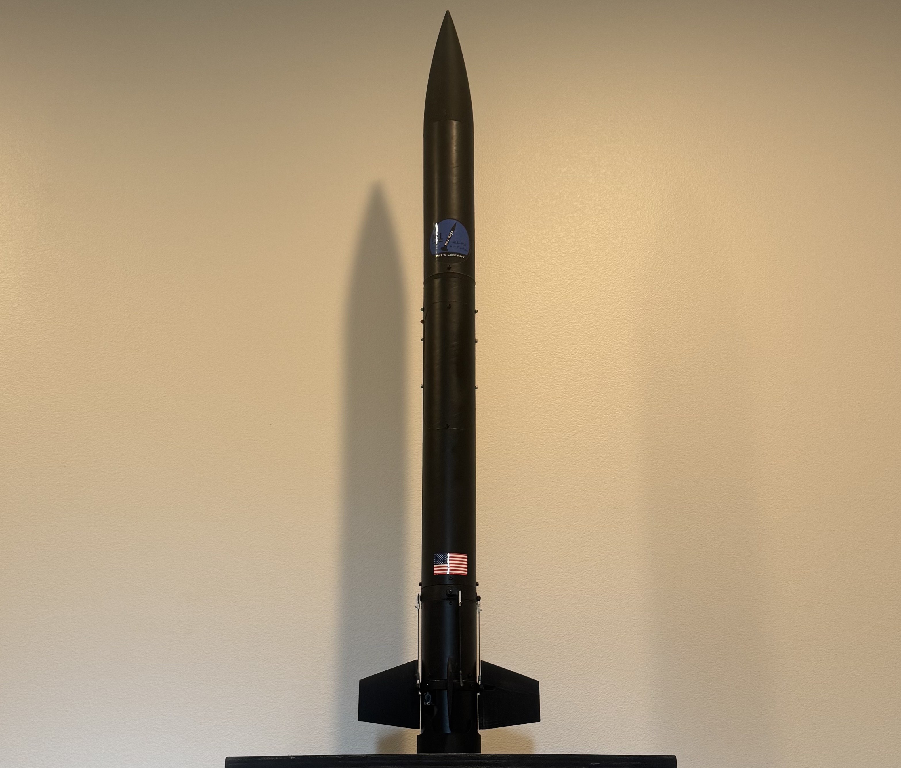
The purpose of this project is nothing special: Simply to expand on a previous project of mine and have fun/learn some things along the way while doing it. Mission Accomplished!
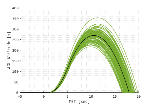
I generated a simple list of requirements for this project. Due to time constraints and priority, not all were met. However, at a high level, they helped me guide the design and write the flight software. Some of these requirements were then used as success checks within the Monte-Carlo simulation environment.
The following PDF documents describe the flight software capabilities that were written for this project. The term "Flight Manager" refers to the main flight computer software that is responsible for igniting the pyros, actuating the TVC, actuating the aft fins, and deploying the parachute.
The following PDF documents describe the aspects of the hardware and monte-carlo desktop simulation of New Mays.
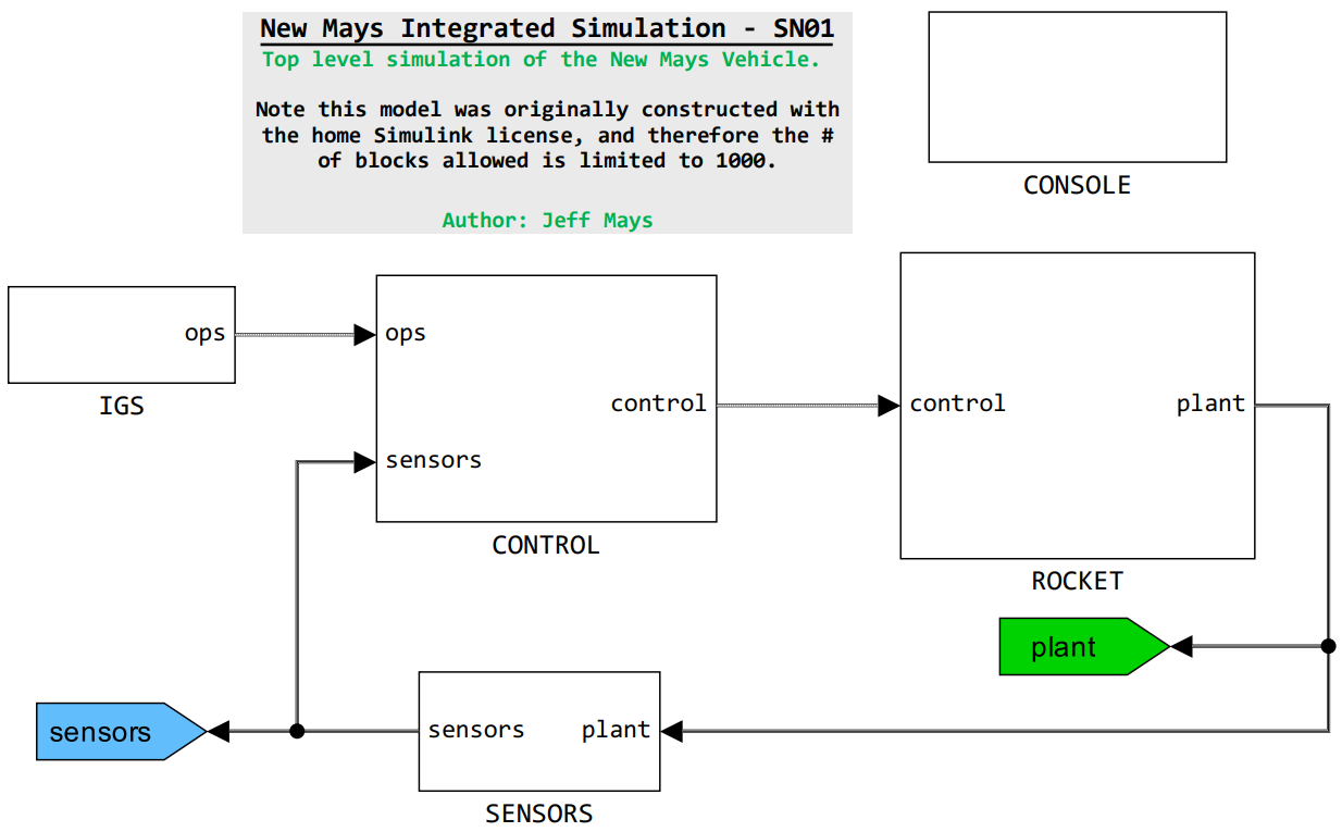
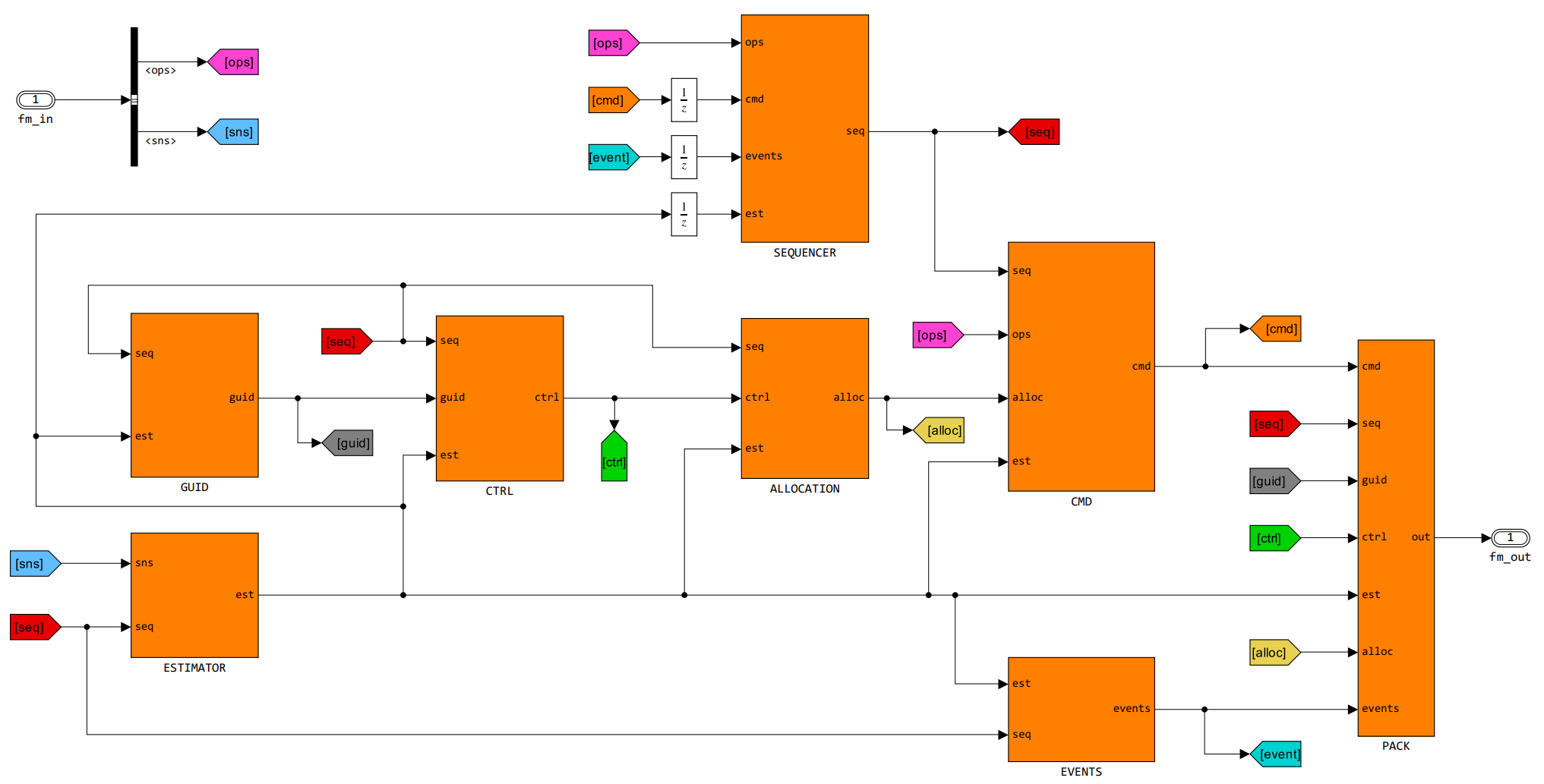
The Monte-Carlo simulation was developed in Matlab/Simulink and included an entire infastructure of SW that initialized, parallelized, post-processed, and plotted the results from flight software and plant model integrated simulations. Below is a top-level of the simulink code. For more information on the simulation, check out the above linked Databooks or contact me directly.
The flight software was originally written in Simulink for prototyping, but then was transformed (manually due to home license) to C/C++ for actual integration with hardware. Tooling was developed to auto-code the interface document into nested C-struct arrays of bus/gain elements for easier integration. The entire flight software package was written as a C++ class object and referenced within the kernal runner for generating the binary. For more information, check out the above linked databooks or contact me directly.
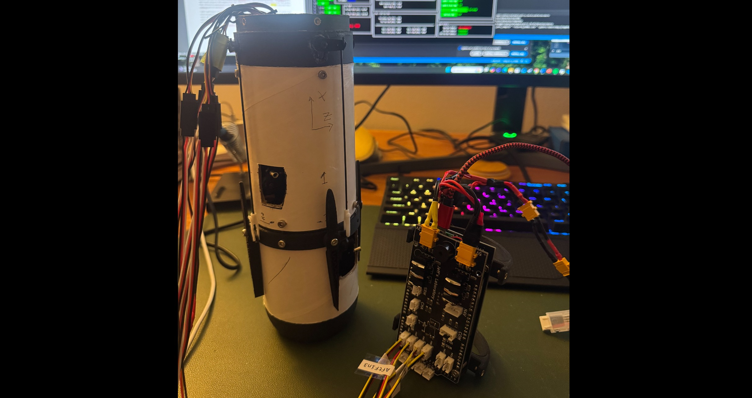
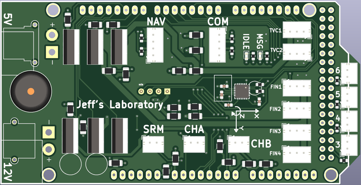
The flight computer was designed in KiCAD and printed using a 3rd party PCB manufacturer. Originally developed as a hat for the arduino DUE, it quickly became apparent that more computing power was needed to perform the necessary flight logic, sensor reads, and wireless communications. The arduino DUO was replaced with a Teensy 4.1 to serve as the main flight brain. The flight software on this board runs at 100Hz. Below is a top view picture of the trivial PCB design.
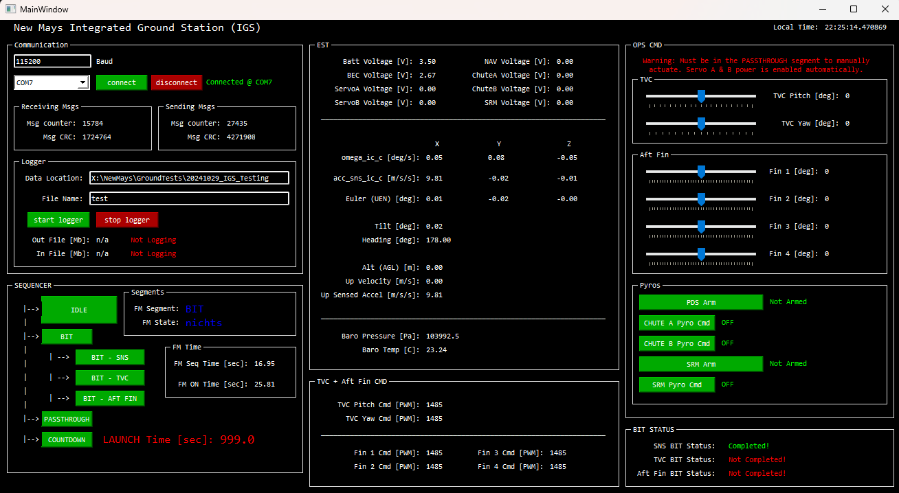
Using Tkinter and pyuic5, I developed an integrated ground station (IGS) where I could wirelessly connect my laptop to the vehicle using 2 Xbee radios. IGS was able to configure the serial ports,
log IO telemetry, command tests and launch sequences, and send/receive the wireless duplex telemetry packets based on calculated/verified CRC checks. If IGS put the flight computer into a manual mode, IGS would
have direct control of all the rocket's effectors and pyro channels (see NMSW01 - Flight Manager Sequencer for
more information on the Sequencer software capability).
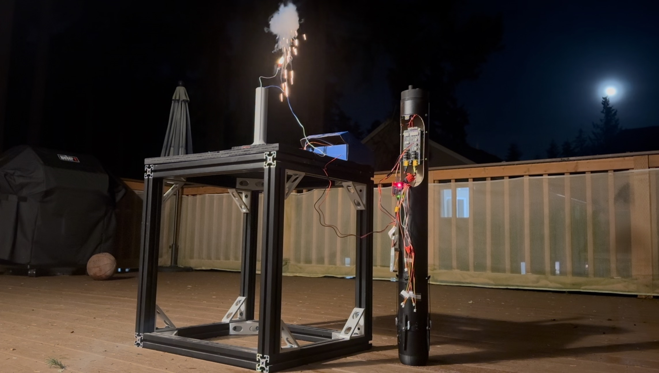
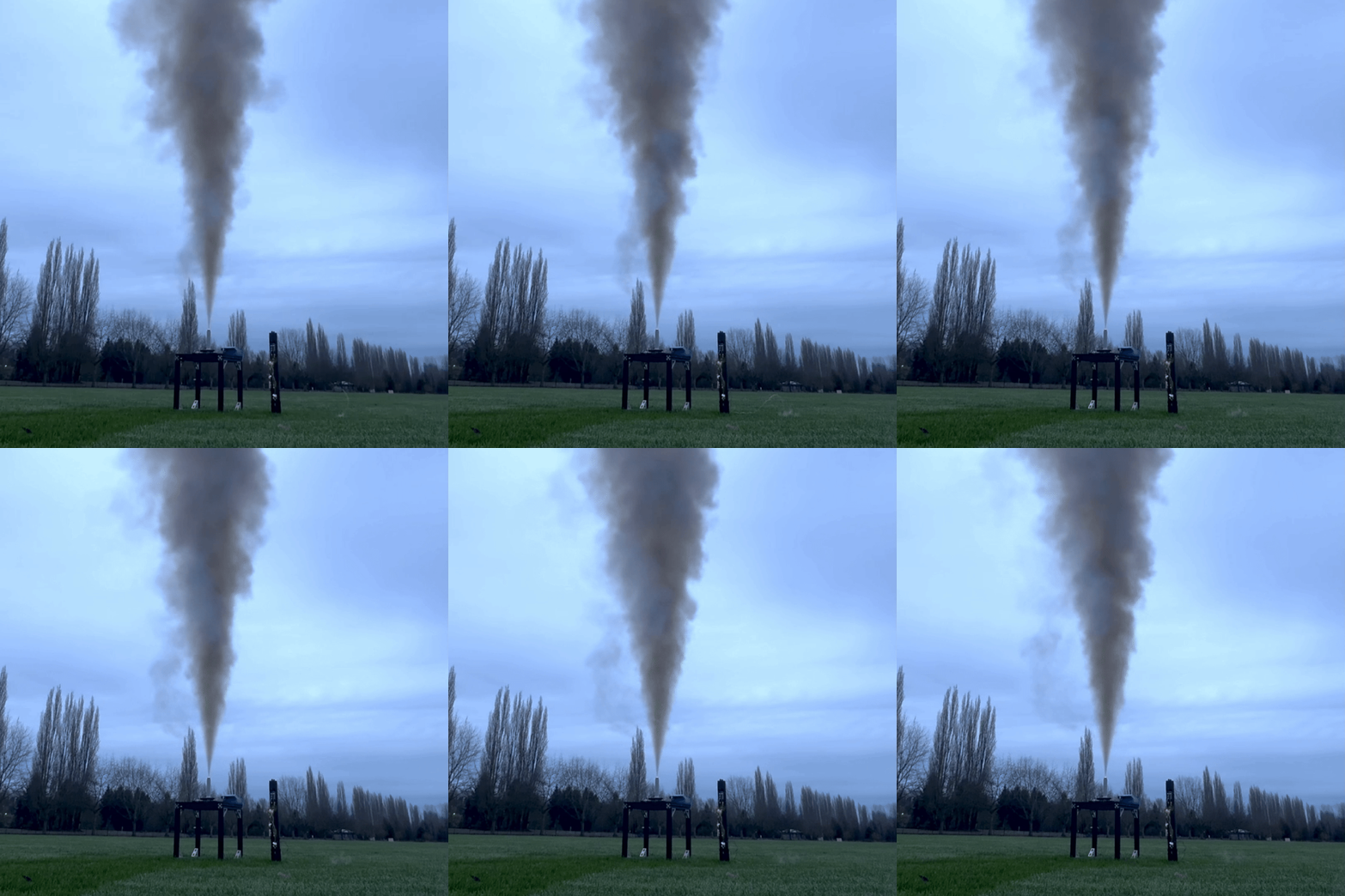
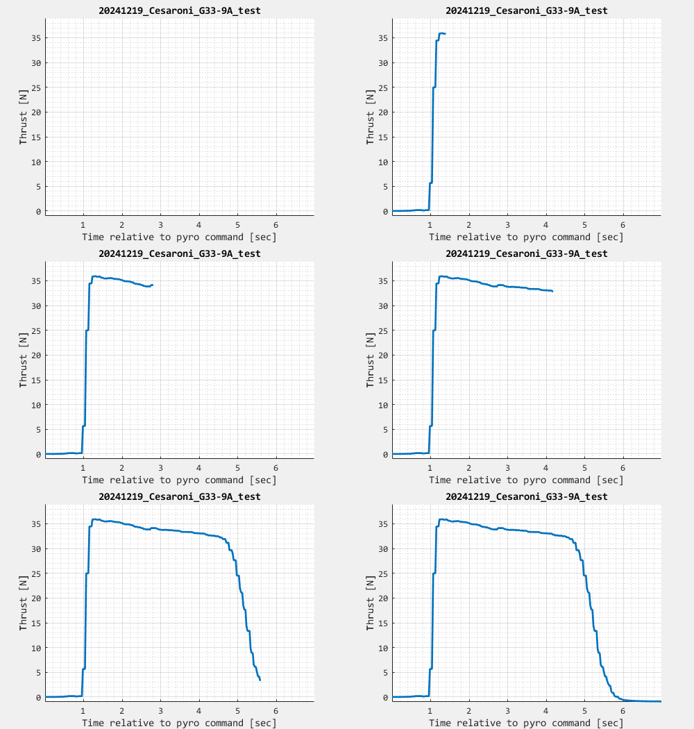
I wanted to characterize the SRM I would be using for the first flight test (which in this case was a Cesaroni G33). I developed a launch pad with load cells that could record thrust data over time, capturing the timeseries thrust profile and pyro-ignition delay time. This data was then used as a baseline set for the Monte-Carlo integrated non-linear simulation and linear stability analysis. More information about this SRM and Hotfire is detailed in NM08 - Solid Rocket Motor Databook .
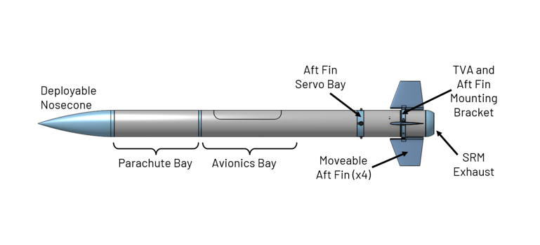
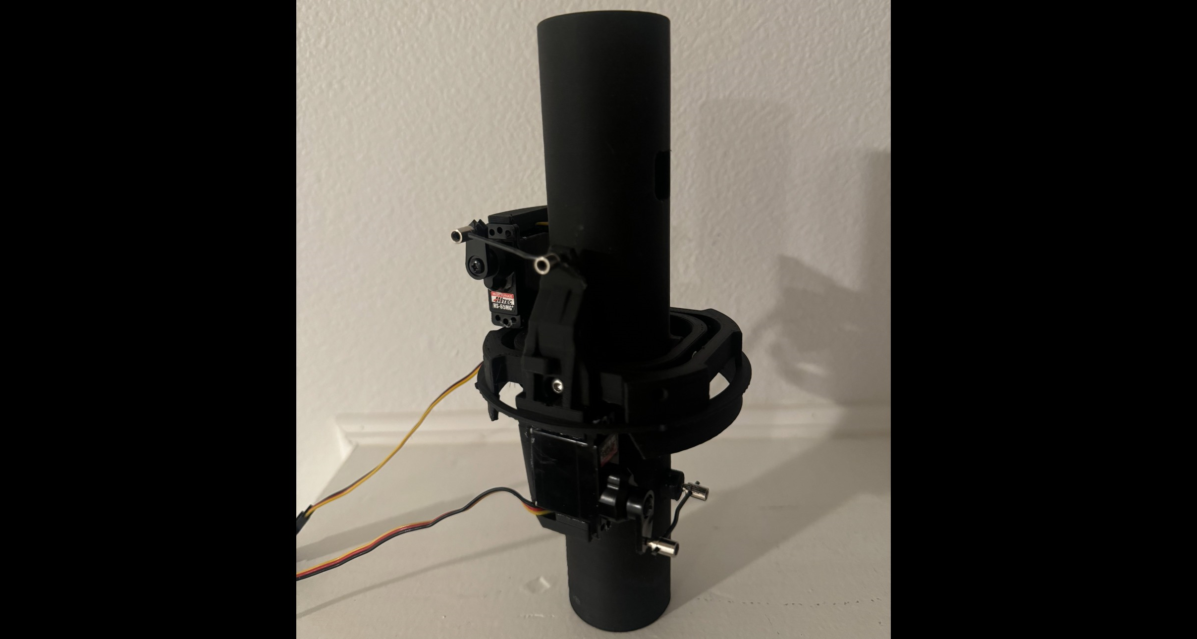
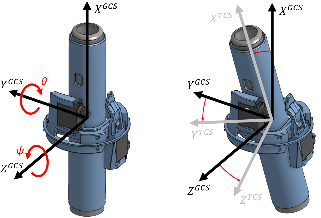
The thrust vector assembly (TVA) is a 3D printed machanism used to vector thrust from an SRM. As the SRM produced thrust, the TVA is able to tilt the SRM in such a way that torques are generated in the rocket's body frame. These torques, if correctly applied, can maintain control over the rocket's state. The TVA is an assembly of 3 parts: outer gimbal, inner gimbal, and SRM sleeve. The outer gimbal controls the pitch axis of the SRM, and the inner gimbal controls the yaw axis of the SRM. The below figure illustrates a CAD rendering of the TVA. Included in the figure is the gimbal coordinate system (GCS) and TVA coordinate system (TCS). The GCS is attached to the outer gimbal and conveniently aligned with the vehicle fabrication frame (FAB). The TCS moves with the SRM sleeve but is nominally aligned with the GCS. The outer gimbal contains the fixed attachment points that fix the assembly into the vehicle. The outer gimbal contains an electro-mechanical servo actuator (servo) to rotate the inner gimbal along the Y^GCS axis of rotation, or θ. The inner gimbal contains a separate servo that rotates the SRM sleeve along the Z^TCA axis of rotation, or ψ. When there is thrust produced in the X^TCS direction, these two sequential rotations can be used to generate a set of desired body pitch and yaw torques. More information about the TVA, including the mathematical model and simulation architecture, is detailed in NM10 - Thrust Vector Assembly Databook.
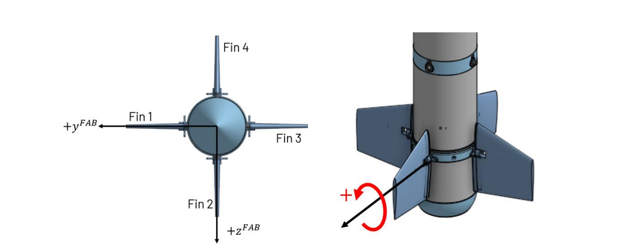
The aft fins are 3D printed fins with a symmetric airfoil (NACA 0008). This fin design uses actuator control rods to manipulate the angle of
the fin relative to the vehicle’s body. Due to the design of the New Mays vehicle, there was not enough space within the outer mold line (OML) of the vehicle to have
these actuating components retained within given the space taken up by the TVA. There is a future design where the servos themselves are retained inside the vehicle aft of the avionics bay, but for SN01 this design is sufficient.
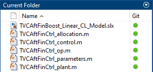
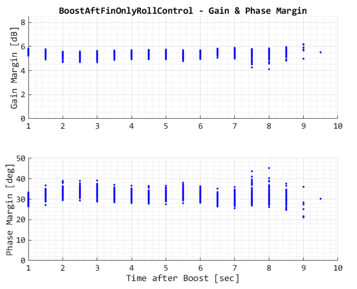
The stability analysis was performed using an in-house tool I made called @StabilityCore. It was used to run and assess the stability of the system at various points using monte-carlo simulation artifacts. For each simulated monte-carlo index, it generated a set of operating points at specific points in time that the tool used to parameterize the closed loop system and provide me with controller artifacts, such as gain and phase margin, or timeseries step reponses.
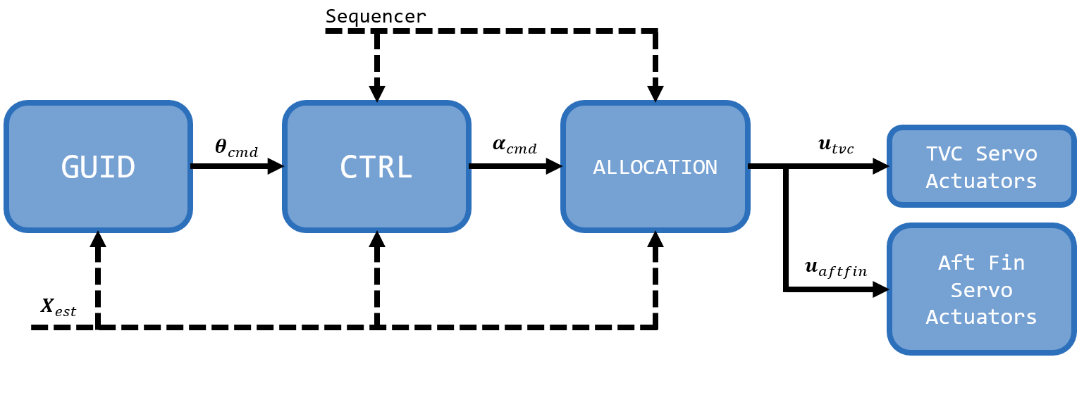
The following block diagram describes the GNC and Allocation architecture of the New Mays model rocket. While the Guidance and Control portions of this model rocket are trivial (simple PD control), the allocation block is of more academic interest.
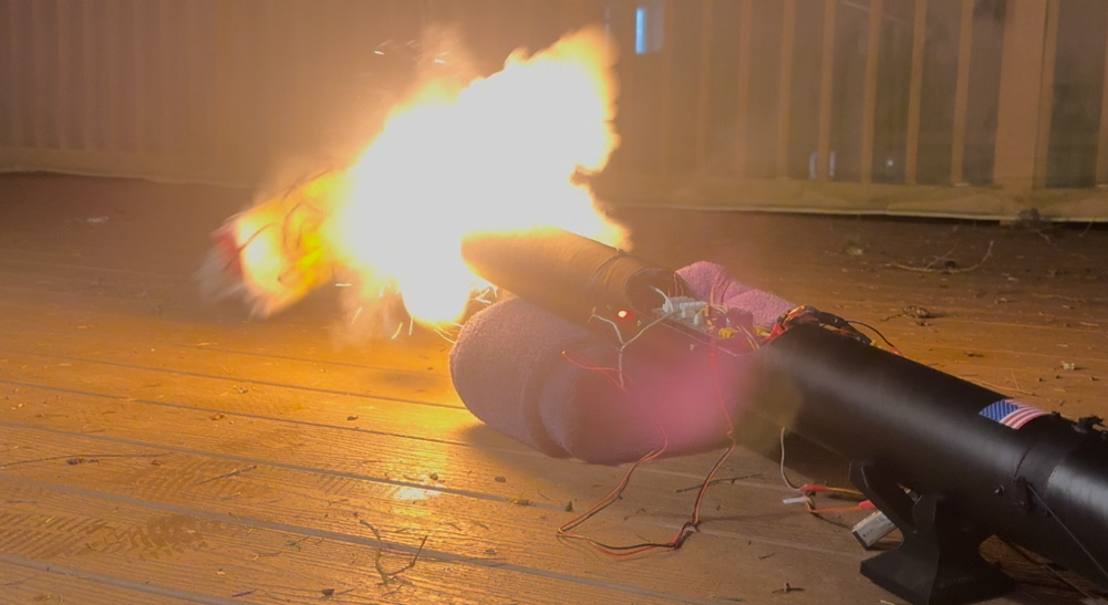
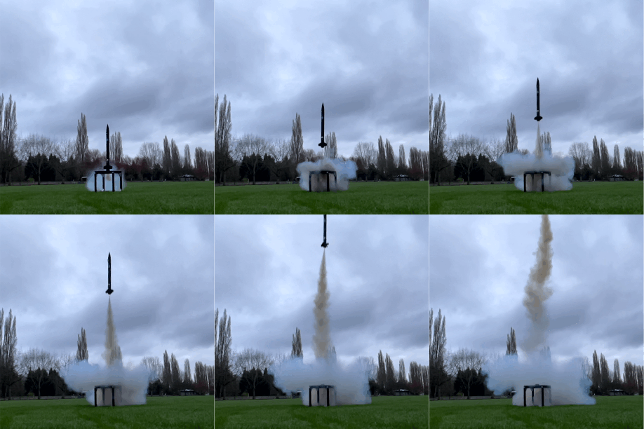
The following video shows most of the flight profile of M1. We can see the rocket go from liftoff at the bottom of the video to an in-flight abort at the top of the video. The in-flight abort is a software capability I integrated and tested in Monte-Carlo and was implemented to reduce the chances of un-wanted cross-range, an important safety precaution. Due to the solid rocket motor's open-loop thrust, I simply deploy the parachute early to try and dampen out the vehicle's energy, which worked successfully. We can see, once the in-flight abort occurs, the parachute deploys and the system has a safe descent to the ground. The reason for the loss of attitude control was later found to be from (A) poorly modeled aerodynamics, causing the system and the controllers to be ill-tuned, and (B) one of the 3D printed TVC arms breaking in mid-flight (at roughly ~50 meters altitude), causing the total loss of attitude control and the ultimate in-flight abort at roughly ~70 meters altitude at Max-Q. Flight data was recorded from the wireless transceivers that were able to corroborate this story. Unfortunately, since the TVC needed to be re-constructed, there was not sufficient time for a re-attempt. This project was exercised as intended, and therefore this project will be taken offline for the foreseeable future to allow me to focus on other endeavors. However, I had a lot of fun and learned a lot! Onto the next project! |
||||||||||||||||||||||||||||

Jeff's LaboratoryThis is a website I use as a tool to document & present my personal projects, particuarly ones that relate to aerospace engineering & robotics. All information contained is either public or owned by me. Specific references will be provided if able.Disclaimer: I accept no responsibility for the use of the information contained within this site. Please use at your own risk! |
